This is the first hardware based project I’ve shared, but this is how I built my ADS-B Tracker.
What’s ADS-B and Why Track It
Most (not all) airplanes are required to broadcast their position as they fly around. This is intended for ATC and other planes primarily, and is another data point in a complex system used to keep these things from running into each other.
These signals can be received on the ground, though, and are what power a number of different flight tracking sites to let you track specific planes, activity around an airport, neat or interesting aircraft you might want to go spot, etc.
Where I live, we have a unique airport that’s civilian, but hosts a lot of visiting military traffic. Planes will come from their base, fly in the pattern for an hour or two and practice landings, then return back to their home base. We see everything from Blackhawk and Chinook helicopters, to E-4Bs, KC-135s, KC-46s and a slew of fighters that come and go.
After seeing lots of missing data on tracking websites for my area for these low, loud, and cool planes I did some research and found there are no receives nearby. Since then, one other receiver has sprung up for some sites in the same city as me, but my receiver is largely the only feeder for these lower airplanes.
To summarize the questions my spouse asked as well:
- Is it legal? Yes, even for the military traffic. There are exceptions where they can (and will) turn off their transmitters.
- Why? Why not? I like looking at planes, other people do too. I’m also nosey.
- Why not just just a service, why run your own? A lot of the services rely on feeders, and other filter out planes. I can also use both, as apps like RadarBox have AR features.
Meta Information
There’s a few things I need to point out before I dive in.
First, the only discount I received for products was a DIY kit from ADSB Exchange. This wasn’t for any promise of content or for me to say good things, this is just because I live near an airport on their priority list. All the other products were purchased with no discounts or incentives, and all the opinions are my own.
Second, I’ll share links to specific products on Amazon. A few items I had on hand and a few I purchased at other retailers. Feel free to purchase things where you’re most comfortable. I just put the Amazon links as they are most accessible.
Third, this is a DIY project and you should have some DIY skills to do it. This isn’t a step-by-step guide, so don’t expect detailed instructions. I’m happy to answer as much questions as I can, but keep in mind tackling this will require a certain level of handy-ness.
Overview
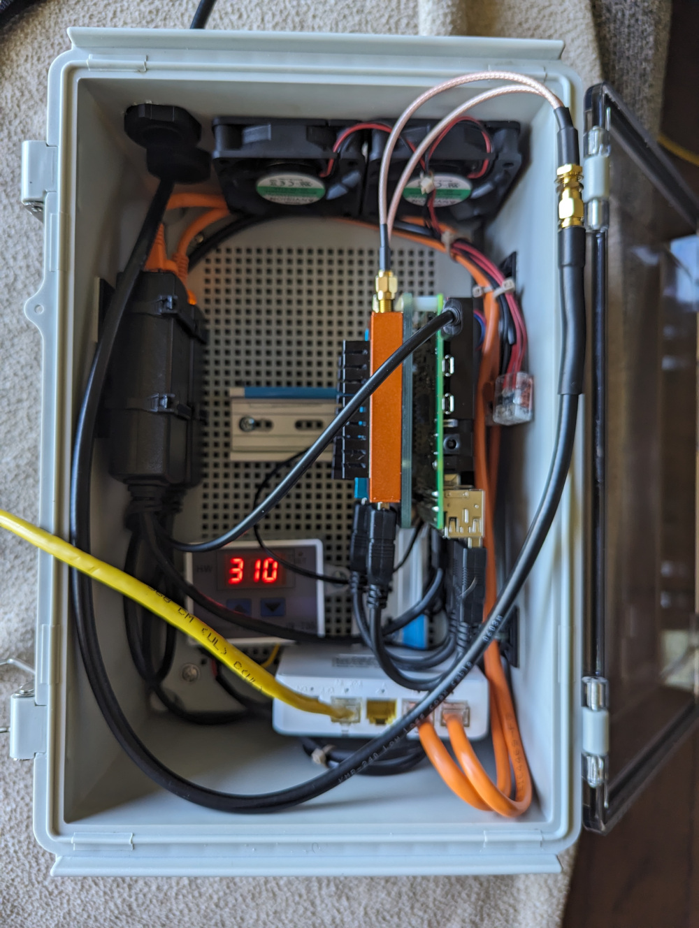
Here’s the semi-finished product. It’s not in its final home quite yet, still finishing some things on the ground before I put it in the garage but right now it boasts about 200nm peak range and we’re seeing all the local flights come and go.
This is designed to mount in the garage with an antenna in the attic. Mounting an antenna outside isn’t really possible in a way my spouse would approve of, and attic mounting removes the risk for lightning, water ingress, etc.
The enclosure is intended to be bug proof at best. There’s no water in the garage, direct sunlight, or tons of dust to worry about. Really, we’re just worried about running into with tools or other things in the garage and larger insects that might want to make a nest in the case.
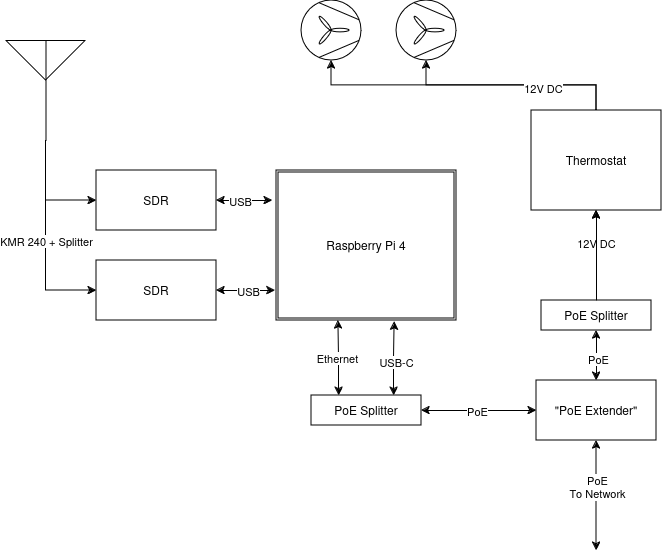
Here’s a block diagram of all the parts:
There’re a few components and systems, so I’ll split it up into talking about each “system.” If there’s parts that are more or less relevant, you can tailor your reading as such.
Enclosure
The enclosure isn’t anything super crazy, just a PVC case with a clear lid.
The enclosure comes with a removable plate pre-drilled with square holes, and I used some button head screws I had laying around to mount the DIN rail to it. The enclosure also comes with wall mounting gear and 2 small cable glands to make things bug proof.
Thoughts here:
- The glands that are included in the enclosure fit our Coax. It can fit Cat5e cable, but with no connector on the end. If you plan on using a pre-made patch cable, you’ll either have to chop the end off and re-terminate it or get a larger gland. A larger gland might start to cause issues with fans, you may need to adjust should you go that route.
- The enclosure is water tight, but we won’t be using it in that way. If you remove the fans and ventilation, you could probably put this in a wet location, though I’m not sure if UV on components would cause further issues.
Parts for this section and notes:
- Enclosure
- A larger enclosure certainly won’t hurt anything. It’s somewhat tight in this size, but it all fits well without issue.
- DIN Rail
- I’m not sure if I got the wrong product delivered, but it’s not 2 pieces as the page implies. It was actually lots of small pieces (which actually worked better since I didn’t have to cut any). 35mm din rail is standard, and this will let us mount some of our parts neatly.
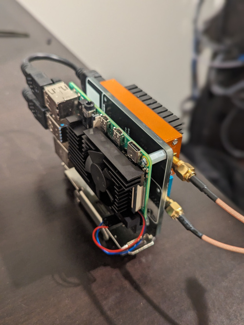
“The Sandwich”
The core is what I’ve dubbed The Sandwich. This is a Raspberry Pi 4, mounted to a DIN Rail Mounting Plate, and two SDRs stuck on the back.
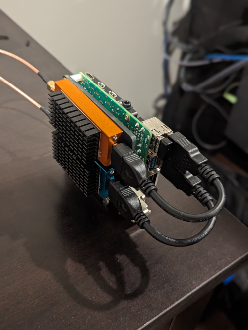
There ins’t much to them, they’re just self contained little units that can run on the bench if needed as well with minimal pain. The idea is to keep these tight and compact, and doing so should allow for two sandwiches in the overall enclosure.
The Pi is screwed to the mount using the included standoffs, and the SDRs are stuck to the back with adhesive tape. The SDRs also have a passive heatsink stuck on the other side to improve overall cooling. The Pi also has a heatsink and fan assembly on it, and this is PWM controlled to allow it to cycle on and off as the Pi gets hot.
Thoughts here:
- Originally I had planned on using a thermal conductive adhesive to stick them to the mount, and use some of the mass of the DIN rail mount to spread heat. The tape I got, while absurdly sticky when cold, turned into a bubblegum type consistency when hot and the SDRs fell off. I went back in with a clear permanent adhesive.
- The SDRs I used just barely fit onto the mount. The mount has some space that is taken up by the transition from the metal part that clips to the DIN rail and the board, so be sure to measure your SDRs to ensure they’d fit.
- You could expand the number of SDRs on a sandwich if you are motivated. I’m not sure if stacking them is advised, or just making some kind of 4-up mount. To keep the same footprint, you’d need to likely remove heat sinks.
- The DIN rail mount and the heatsink on the Pi aren’t exactly compatible. The heatsink screws from the bottom, through the Pi, and into the metal. The mount wants you to screw from the top down into a plastic standoff. You can probably work around this with different screws and configurations, but 2 seems to be OK enough for now.
- Before sticking the SDRs to the mount, make sure you aren’t having to twist the USB cables. It looks much better when you don’t have to twist the cable 180 degrees, as they’ll naturally want to sit in a particular orientation.
Parts for this section and notes:
- Raspberry Pi 4
- I have a 2GB version. It boots from iSCSI and is pretty vanilla overall.
- GeekPi Heatsink
- This is able to be controlled via a PWM pin on the Pi, and using
raspi-config, you can set a temp to start/stop the fan at.
- This is able to be controlled via a PWM pin on the Pi, and using
- DIN Rail Mount
- I was kinda surprised at how sturdy this mount is. Compared to some of the plastic options I saw online, this seemed pretty bullet proof. Has quite a bit of mass too, and I figure it can help soak some of the heat out of the SDRs on the back.
- USB Extension
- SDRs
- One is the blue 1090 MHz model, one is the orange 978 MHz model. These two fit perfectly on the back of the Pi’s mounting plate.
- Heatsinks
- Fit perfectly on the SDRs.
- SMA Splitter
- There’s tons of options for splitting RF. I went with a simple splitter cable, but there are tons of options.
- Adhesive
- There’s a ton of options again, I went with this stuff since I’ve used it before and it’s pretty strong. I’ve seen that some adhesives lose their stick when the SDRs get hot, so keep that in mind. It’s not a huge deal if they come off either, but it keeps things tidy.
Network / Power
My unit is powered from a PoE+ port on my switch. This removes the need for AC power where I mount it, and since my switch is on a UPS, this receiver will be on a UPS as well.
If you’ve never dealt with PoE equipment, know that there’s a difference between PoE (802.3af), PoE+(802.3at) and other standards (passive PoE, 802.3bt). I’m not sure if this will work with PoE and not PoE+, I’d just recommend using PoE+ (or PoE++, it’ll just operate at PoE+) injectors and equipment. It run about 15 watts now (the max PoE budget), and another Pi would put us squarely into PoE+ territory.
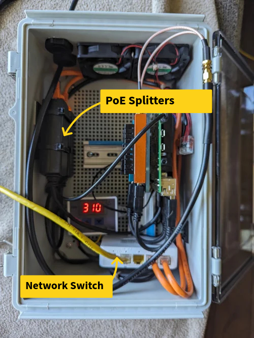
Since the enclosure supports two sandwiches and we’d like some voltage for fans and cooling, I opted for a PoE switch in the enclosure. The unit I found is labeled a “PoE Extender”, but it really is a PoE powered switch. It can take 30 watts in and provide up to 25 watts out, all on one port if needed.
We then run into two PoE splitters. One outputs a USB-C plug for the Pi (I’ve extended it as well since taking photos to reduce some of the strain on the cord). The other outputs 12 volts in a barrel plug for our fans (more later).
Thoughts here:
- The PoE switch is mounted sideways on a vertical piece of DIN rail tucked in the bottom. It might be hard to see, but it’s tucked back behind everything and lets the switch hang down but not sit on the bottom and block the vents.
- The DIN rail clips on the switch are quite loose. I got some thing adhesive foam and stuck it to the DIN rail to keep it from sliding.
- The splitters are mounted to the side using adhesive zip tie mounts and zip ties. You could probably tape these or do something more fun, but the zip ties work fine.
Parts for this section and notes:
- PoE Switch
- This model has a switch that’s labeled “On/Off” and looks like a power switch, but really toggles some VLAN tagging on ports. I bring it up because it’s not really labeled on the unit, looks like a power switch, and turning it on will probably break connectivity.
- Cables
- Normal Cat5e works here. I wouldn’t worry about shielding (there’s no good way to ground it with these parts anyway), and don’t get too fancy of cable. It’s tight in the box, and thicker cable like Cat 6A, outdoor rated, etc might not fit without damaging things. For PoE+ and higher wattage, there’s some debate about if “slim” cables are safe. I stuck with “normal” 24awg cables for this application.
- USB-C PoE Splitter
- 12V PoE Splitter
Fans
Since my garage gets hot, I opted for active cooling for this setup. This, again, makes things not water proof or dust proof, but neither were concerns for my setup.
I went with 60mm fans since they fit well on the case and I had a hole small that’s the right size. Drilling into the PVC is easy with a basic battery drill. I used a 2.25" hole saw for the main holes and it worked fine.
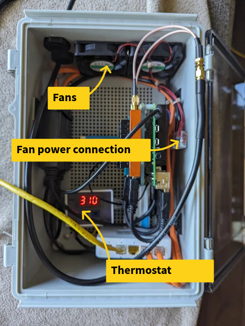
To power the fans, we’ll take 12 volts from our PoE Splitter. I don’t want the fans to run all the time, since that will cause me to replace them more often, make dust worse, and most of the time the temperature should be fine. I went with a digital thermostat for this, there are mechanical options that require no power and other digital options, but I liked the look and feel of the one I got.
I used some low-temp solder heat-shrink connectors to connect the thermostat’s input (red and black wires, red is positive) to the barrel connector. I then did the same to some wire to extend the output up to the top of the enclosure and use Wagos to connect to the fans. Since the fans will someday fail, I figure a Wago is easy to change out without having to break out a soldering iron and working on the wall.
To program the thermostat, hold the up or down arrow until the numbers flash. Then use the up and down arrows to set a value. After a few seconds, it’ll be saved. This unit can heat or cool, and you can set how the hysteresis you’d like. To cool, set a start number (the one programed with the up arrow) to when you’d like the fans to start. Set the stop value (the one programmed with the down arrow) to a value lower.
I tucked the temperature probe between the two SDRs since they seem to be the hottest components. The start temp is set to 48 degrees, and the stop temperature is 35 degrees. My goal is to run the fan fairly infrequently and run it for a few minutes at a time. Sitting inside the fans run once every few hours for about a minute.
After pictures, I also drilled two holes on the bottom to act as an exhaust, while the fans intake air above. If you don’t have a place for the air to escape, the cooling won’t work very well.
Thoughts here:
- You’ll want to make sure you clean the holes when done drilling them. The PVC can leave burrs that will jam the fan blades.
- I don’t have good suggestions for drilling the holes. Mine don’t look good, but they’re covered by the fan screens anyway.
- One fan might be enough. The fans I got move quite a bit of air.
- I stuck the temperature probe between the two SDRs and stuck it to the DIN rail mount for Pis with a dollop of hot glue. I checked the temperature using a infrared thermometer to make sure they weren’t too hot. Make sure you verify things to ensure the temperature probe is getting a semi accurate temerature.
Parts for this section and notes:
- Thermostat
- The black and red are the input, black and yellow is output. Black is always ground on this unit. I wired the black and red input to the barrel jack, and the yellow and black output to the fans. There’s no need to combine wires or tie things together.
- 60mm Fans
- These fit nice on the enclosure. If you opt for other sizes, make sure they’ll fit on the enclosure still. These have a connector, but I just clipped it off and use the bare wires.
- 60mm fan screens
- Mostly for bugs, not dust. Though I think these will keep the bigger dust parts out.
- DC Barrel Plug
- This fits into the PoE splitter’s jack perfect.
- Wire / Connectors
- You’ll probably want some wire to extend the output up for the fans. The input side has enough length to not need extension. Also keep in mind the fans will die someday, and you probably don’t want to drag out your soldering iron and solder things in odd places.
RF Components
The RF side is pretty easy. We’re running a dual 1090/978 MHz antenna to get both ADS-B and UAT transmissions. We split the signal so we can use one antenna and both SDRs.
I don’t have a lot of insight here as I’m not very knowledgeable on RF things. These parts worked for me.